VERTICAL DELTA LOOPS
Just as the inverted-V dipole has been described as the poor man’s dipole, the delta loop can be called the poor man’s quad loop. Because of its shape, the delta loop with the apex on top is a very popular antenna for the low bands; it needs only one support.
In free space the equilateral triangle produces the highest gain and the highest radiation resistance for a three-sided loop configuration. As we deviate from an equilateral triangle toward a triangle with a long baseline, the effective gain and the radiation resistance of the loop will decrease for a bottom corner-fed delta loop. In the extreme case (where the height of the triangle is reduced to zero), the loop has become a half wavelength-long transmission line that is shorted at the end, which shows a zero-Ω input impedance (radiation resistance), and thus zero radiation (well-balanced open-wire line does not radiate). Just as with the quad loop, we can switch from horizontal to vertical polarization by changing the position of the feed point on the loop. For horizontal polarization the loop is fed either at the center of the baseline or at the top of the loop. For vertical polarization the loop should be fed on one of the sloping sides, at λ/4 from the apex of the delta. Fig 10-8 shows the current distribution in both cases.
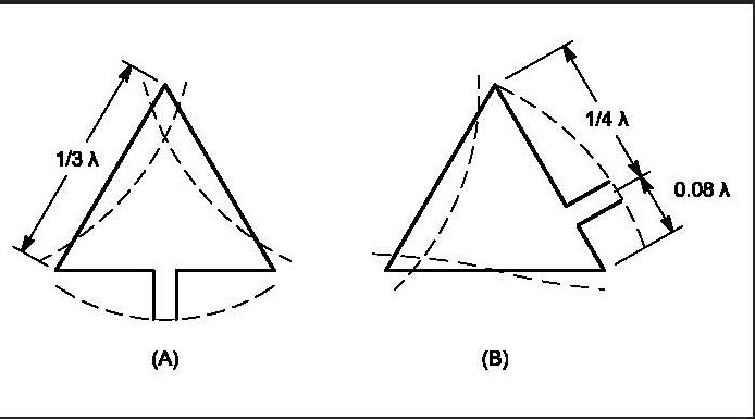
Fig 10-8—Current distribution for equilateral delta loops fed for (A) horizontal and (B) vertical polarization.
2.1. Vertical Polarization
2.1.1. How it works
Refer to Fig 10-9. In the vertical-polarization mode the delta loop can be seen as two sloping quarter-wave verticals (their apexes touch at the top of the support), while the baseline (and the part of the sloper under the feed point) takes care of feeding the “other” sloper with the correct phase. The top connection of the sloping verticals can be left open without changing anything about the operation of the delta loop. The same is true for the baseline, where the middle of the baseline could be opened without changing anything. These two points are the high-impedance points of the antenna. Either the apex or the center of the baseline must be shorted, however, in order to provide feed voltage to the other half of the antenna. Normally, of course, we use a fully closed loop in the standard delta loop, although for single band operation this is not strictly necessary.
Assume we construct the antenna with the center of the horizontal bottom wire open. Now we can see the two half baselines as two λ/4 radials, one of which provides the necessary low-impedance point for connecting the shield of the coax. The other radial is connected to the bottom of the second sloping vertical, which is the other sloping wire of the delta loop.
This is similar to the situation encountered with a λ/4 vertical using a single elevated radial (see Chapter 9 on vertical antennas). The current distribution in the two quar
ter-wave radials is such that all radiation from these radials is effectively canceled. The same situation exists with the voltage-fed T antenna, where we use a half-wave flat top (equals two λ/4 radials) to provide the necessary low-imped ance point to raise the current maximum to the top of the T antenna.
The vertically polarized delta loop is really an array of two λ/4 verticals, with the high-current points spaced 0.25 λ
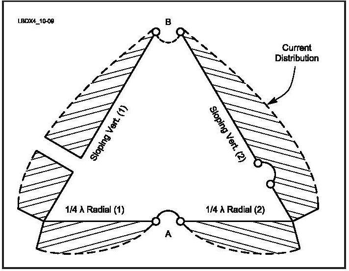
Fig 10-9—The delta loop can be seen as two λ/4 sloping verticals, each using one radial. Because of the current distribution in the radials, the radiation from the radials is effectively canceled.
For more on this see ON4UN Low-Band DXing
Credits ON4UN Low - Band DXing